
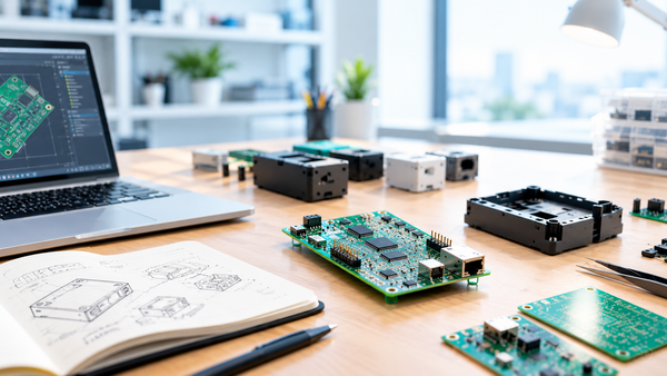
Electronic Prototype Development: The Complete Process from Idea to Series Production
Many electronic prototypes work on the bench and still never reach series production. The reasons are rarely the idea itself: the specification was incomplete, components were chosen without a view on availability, nobody planned how the board would be tested in production, or the design was never documented well enough for the next team to continue.
Many electronic prototypes work on the bench and still never reach series production. The reasons are rarely the idea itself: the specification was incomplete, components were chosen without a view on availability, nobody planned how the board would be tested in production, or the design was never documented well enough for the next team to continue.
This guide walks through the complete prototype development process for electronics, phase by phase: what happens, which results each phase must deliver and which mistakes cost the most. A real project, the modernisation of the LudwigHook crane hook system for LUDWIG SYSTEM, shows how a structured approach turns a grown, undocumented system into a solid basis for further development.
The process at a glance
Professional prototype development runs through six phases. Each phase ends with a defined result and a decision: continue, change or stop. These gates are what keep cost and risk under control.
| Phase | Key question | Result (deliverable) | Gate decision |
|---|---|---|---|
| 1. Requirements and specification | What exactly must the product do, where and for how long? | Requirements specification | Is the specification complete enough to estimate? |
| 2. Concept and architecture | How will we build it? | Block diagram, platform choice, make-or-buy, risk list | Is the concept technically and economically sound? |
| 3. Hardware design | Is the circuit correct and manufacturable? | Schematic, bill of materials, PCB layout, design review | Release for the first build |
| 4. Firmware and software | Does the system behave as specified? | Software architecture, drivers, application, test software | Functional release |
| 5. Samples and pilot series | Does it work, and can it be built repeatably? | A-, B- and C-samples or pilot series | Release for series production |
| 6. Validation and series transfer | Does it meet all requirements and standards? | Test reports, EMC results, production test concept, documentation | Start of series production |
Phase 1: Requirements and specification
Everything that follows builds on this phase. The goal is a requirements specification that answers what the product must do, under which conditions and in which market.
What it must cover:
- function and performance, including measurable limits
- operating environment: temperature range, humidity, vibration, shock, ingress protection
- power supply: voltage range, transients, battery operation, power budget
- interfaces to the outside world: fieldbus, industrial Ethernet, CAN, RS-485, USB, wireless, display and touch
- applicable directives and standards for the target markets
- expected series volume, product lifetime and service concept
Typical mistake: starting development with a list of features instead of measurable requirements. Every open point becomes an assumption or a later change.
Phase 2: Concept and architecture
In the concept phase, the requirements are turned into a technical structure. This is where the most important cost and risk decisions are made.
- System architecture: division into functional blocks such as power supply, controller, sensors, communication and HMI, with defined interfaces between them.
- Platform choice: microcontroller, embedded processor or FPGA; bare-metal, RTOS or embedded Linux.
- Make-or-buy: which functions are developed, which are covered by proven modules or bought-in components.
- Software structure: module boundaries and interface contracts, so hardware and software can be developed and tested independently.
- Communication concept: internal protocols between subsystems and external protocols to devices, controllers or base stations.
- Risk list: technical uncertainties that must be clarified early, for example with a proof of concept.
Typical mistake: skipping the concept and going straight to the schematic. Without a documented architecture, every later change affects the whole system.
Phase 3: Hardware design
The hardware design turns the concept into a schematic, a bill of materials and a PCB layout.
- Schematic design with calculation of power supplies, protective circuits and analog front ends.
- Component selection with a check of availability, lifecycle status, temperature grade and second sources.
- PCB layout: stack-up, impedance control for high-speed signals, separation of analog, digital and power areas, thermal design, creepage and clearance distances.
- Design for EMC: filtering, grounding and shielding concepts planned from the first layout.
- Design review before the first build: schematic and layout are checked against the requirements and manufacturing rules.
Typical mistake: choosing components only by function and price. A part that is discontinued two years after launch forces an expensive redesign.
Phase 4: Firmware and software
Firmware turns the hardware into a working product. It often accounts for a large part of the development effort.
- board support and drivers for all peripherals
- application logic, state machines and error handling
- communication stacks and protocols
- user interface on displays and touch panels
- update mechanisms, security functions and logging
- test software for development and for production testing
Typical mistake: writing firmware without clear module boundaries. Code that grows without structure becomes hard to test, extend and hand over.
Phase 5: Samples and pilot series
Most electronics projects go through several build stages. Each stage has a different purpose.
| Build stage | Purpose | Built with | Main tests |
|---|---|---|---|
| Proof of concept | Clarify one technical risk | Evaluation boards, lab setups | Feasibility of the critical function |
| A-sample (functional sample) | Prove that the design works | First PCB, prototype assembly, simple mechanics | Functional tests, first measurements, EMC pre-compliance |
| B-sample (design sample) | Prove that the design meets the requirements | Revised PCB, near-series mechanics | Environmental tests, extended EMC tests, field tests |
| C-sample / pilot series | Prove that it can be built repeatably | Series processes, test fixtures, documentation | Production tests, qualification, approval tests |
Typical mistake: skipping the pilot series. Problems with assembly, testing or documentation then appear in the first series batch, where they are most expensive.
Phase 6: Validation and series transfer
Before series production starts, the product must prove that it meets all requirements and that it can be produced and tested reliably.
- functional and environmental tests against the specification
- EMC and safety tests for the target markets, for example as basis for CE marking in the EU
- production test concept: test points, test fixtures and test software
- complete documentation: schematics, bill of materials, manufacturing and test instructions
- plan for lifecycle support: spare parts, repairs and obsolescence management
Design for manufacturing and test: think about the series from day one
A prototype is only valuable if it leads to a product that can be manufactured. That is why manufacturing and test requirements belong in the first layout, not in the last.
- DFM (design for manufacturing): component placement and spacing, panelisation, fiducials, solderability and assembly sides.
- DFT (design for test): accessible test points, programming interfaces, self-test functions in the firmware.
- Documentation: a design that only its original developer understands is a risk for every later change.
Long-term availability starts with the first prototype
Industrial and medical products often stay on the market for ten years or more. The components chosen for the first prototype decide whether that is possible without a redesign. Checking lifecycle status and second sources during component selection, and planning obsolescence management from the start, protects the investment in development.
Real project: how LUDWIG SYSTEM rebuilt the basis for the LudwigHook
The LudwigHook from LUDWIG SYSTEM is a radio-controlled load hook for mobile, tower and port cranes, used indoors and outdoors. It is available in a standard version for up to 2.5 t and an XL version for up to 5.3 t, communicates at 868 MHz with a range of around 50 m, and runs on a rechargeable battery with its own charging station.
Initial situation
Over the years, the electronics and software had grown without a consistent architecture or structured documentation. An earlier external development on a time-and-material basis had not delivered the desired result. LUDWIG SYSTEM was looking for a partner who would first understand and document the existing system before writing new code.
Approach: a concept phase with four work packages
Instead of starting with new code, the project began with a structured concept phase. It was divided into four work packages, each with its own result. This allowed LUDWIG SYSTEM to decide package by package how to proceed.
| Step | What was done | Result | Status |
|---|---|---|---|
| 1. Hardware concept | Electronics architecture at block level: power supply, sensors, radio module, interfaces | Documented hardware architecture | Completed |
| 2. Software concept | Module boundaries and interface contracts in the firmware | Structured software architecture | Completed |
| 3. Internal communication protocol | Data exchange between the subsystems inside the hook | Defined internal protocol | Completed |
| 4. Radio protocol | Communication between hook, remote control and base station | Defined radio protocol | Completed |
| 5. Revision of the electronics | Electronics revised along the new structure, each work package serving as a verified basis | Revised electronics on a documented foundation | In progress |
| 6. Further product lines | Extension to further product areas, up to the entire portfolio | Joint project horizon until January 2028 | Planned |
What this project shows for your development
- Concept before code: even for an existing product, a documented architecture is the fastest way to reliable changes.
- Work packages with their own results: each package delivers something usable and gives you a clear decision point.
- Documentation is part of the product: it makes the system maintainable, extendable and independent of individual developers.
- A foundation for the long term: a structured basis allows further product lines to build on the same architecture.
Read the full case study: LUDWIG SYSTEM – Kranhaken trifft Embedded Electronics.
Checklist: is your prototype ready for series production?
- The requirements specification is complete, agreed and under version control.
- The architecture and interfaces are documented.
- All components have been checked for availability, lifecycle status and second sources.
- DFM and DFT rules are implemented in the layout.
- EMC pre-compliance measurements have been carried out and evaluated.
- Firmware is structured in modules and its interfaces are documented.
- A production test concept with test points and test software exists.
- A pilot series has been built and evaluated with series processes.
- The documentation is complete enough for a third party to manufacture and maintain the product.
- Spare parts, repairs and obsolescence management are planned.
If you cannot tick every point yet, that is normal at the prototype stage. The checklist shows where the remaining risks are, and where a structured engineering partner can help.
How T&O Electronic Solutions supports you from idea to series
T&O Electronic Solutions has developed and built electronic systems since 1990, for more than 800 customers in industrial and medical technology.
- Free initial consultation and support with your requirements specification.
- Concept and architecture work that creates a documented basis before development starts, as in the LudwigHook project.
- Custom hardware and software from one team, based on proven, reusable building blocks.
- Prototypes, small and pilot series and series production, in-house or with qualified manufacturing partners, with one contact person for the whole project.
- Long-term support: obsolescence management, repairs and spare-parts supply.
- Displays and HMIs from our own Display Solutions unit.
- Quality management certified to ISO 9001, with sites in Hausham (Germany) and Ramsen (Switzerland).
Want to know what your project costs? Read our article "How Much Does Electronic Prototype Development Cost? Factors, Ranges and Saving Tips".
Frequently asked questions
How long does electronic prototype development take?
It depends on the maturity of the specification, the complexity of hardware and firmware, component availability and the number of build stages. A realistic schedule is created together with the estimate, after the requirements have been clarified.
What is the difference between an A-sample, B-sample and C-sample?
The A-sample proves that the design works. The B-sample is a revised design close to the final product and is used for extended tests. The C-sample or pilot series is built with series processes and proves that the product can be manufactured repeatably.
Can you take over an existing product that was developed elsewhere?
Yes. As in the LudwigHook project, the first step is to understand and document the existing system. On that basis, the product can be revised, extended or moved to available components.
When does a concept phase make sense?
Almost always, and especially for complex systems, for products with safety-relevant functions and for existing products without documentation. A concept phase with defined work packages gives you clear results and decision points before larger investments are made.
Do we need a pilot series?
For products going into series production, yes. A pilot series shows whether assembly, testing and documentation work under series conditions, before the first series batch is built.
Who owns the design after development?
Ownership of schematics, layout data and source code is defined in the development contract. Clarify this before the project starts.
Can development, prototyping and series production stay with one partner?
Yes. Keeping one partner from concept to series avoids hand-over losses between design house, layout service and manufacturer, and keeps the knowledge about the product in one place.